![[Image] , 13887 byte(s).](bfectxt6_1.gif)
PART 1
The following information and photos have been furnished by
Bill Wood. Bill over the years has been active in many areas of
the old BFEC including Bendix RSD, Hawaii; MSFN NST GSFC;
Goldstone MSFN and Goldstone DSN. Bill has also furnished some
very interesting links to Pacific Missile Range programs and you can
find these on the "LINKS" page of the BFEC HOMEPAGE.
Many thanks to Bill for this input.
----------------------------------------------------------------------------------
Some follow-up information about the role of the DSN 64-meter antenna during
the Apollo lunar missions.
In early 1969 NASA requested JPL to provide the 210 foot diameter Mars
(DSS-14) antenna at Goldstone for backup support of the upcoming Apollo
missions to the Moon. Mars (which was named after receiving it's first
signals from Mariner 4 at on the way to Mars) could detect a signal 10 times
weaker than the 85 foot diameter MSFN antenna at Goldstone.
Collins Radio was contracted to install a microwave link between the Apollo
station and Mars that would transfer the voice and data signals from the
Apollo spacecraft from DSS-14 to the signal processing equipment at the MSFN
station. I have attached two photos showing the stations and their
terrestrial microwave dishes. The link installation was completed in June
of 1969 just in time for Apollo 11.
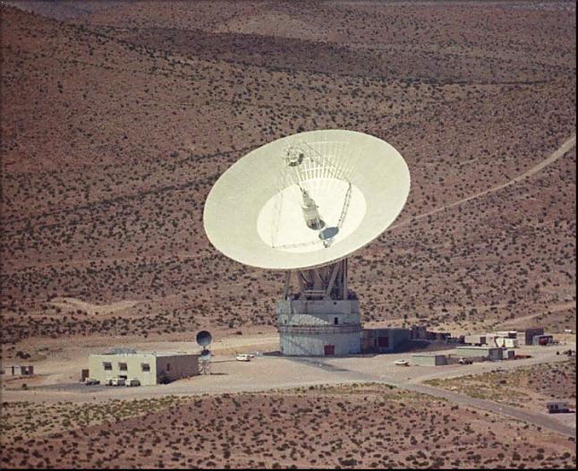
The DSS-14 photo (C066-5-2mr.jpg) was taken from the hilltop site of the
C-band microwave passive repeater (two 15-foot dishes connected
back-to-back). This shows the newly constructed operations building with
it's microwave dishes pointed directly at the camera. The larger top dish
was for the circuit to the MSFN station. The smaller dish was an X-band
circuit back to the DSN communications center at the Echo site some 15 miles
to the east.
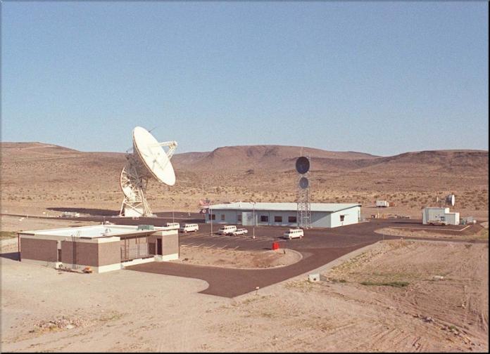
In the MSFN station photo (C088-3-4mr.jpg) you can see the corresponding
microwave link antennas on the tower near the right edge of the large
operations building. Again the larger top antenna is the C-band unit
directed to the passive repeater located on a hilltop between it and the
Mars station. The smaller X-band dish was for communications with the
Pioneer MSFN Wing station. The small building and microwave dishes at the
right side of the photo is the telecomm microwave terminal with it's dual
path circuits to Goddard Space Flight Center and Houston.
When the Manned Space Flight Network was first planned NASA decided to use
only proven equipment for communications with the Apollo spacecraft. To
that end JPL's Block III S-band receiver-exciter system was chosen for the
task. Motorola built an additional 30 systems for use in the MSFN. The
BK-III receivers were also used at the DSS-14 station so no additional
equipment was needed. The MSFN operating frequencies of 2282.5 and 2287.5
MHz were below the normal DSN range of 2290 to 2295 MHz, so a slight
retuning of the low noise amplifiers was needed.
The S-band system at the Mars station used traveling-wave maser low noise
amplifiers that were cooled with liquid helium, producing a receiver system
temperature of 15 degrees Kelvin, considerably below the 100 degree K system
temperature at the Apollo station. This, coupled with the increased gain of
the larger antenna, produced the 10 dB signal improvement. The S-band maser
was installed in the feedcone of the antenna to keep the signal loss down
between the feed horn and the amplifier. Prior to each Apollo support the
maser was retuned down to the MSFN operating frequencies.
The maser provided some 50 dB of signal amplification before the receiver
front end. The receiver local oscillator and first mixers were located in a
space right below the feedcone to minimize signal loss. The receiver 50 MHz
intermediate frequency was carried down to the control room some 500 feet
away by low-loss coaxial cable.
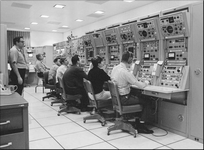
I have also attached a photo showing the dual JPL Block III receiver-exciter
controls at the Prime station (156-2-4mr.jpg). Each system had a control
rack for the exciter and two receiver control racks for each. Thus you see
six racks making up the two systems. Two were used for redundancy and to
allow communications with both the CSM and LM at the same time through a
signal antenna.
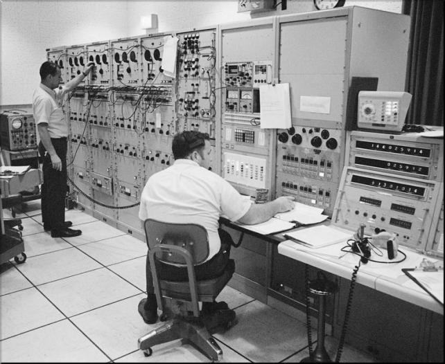
The Mars station was equipped with a single BK-III receiver-exciter which
fed it's baseband PM demodulated signal over a microwave video circuit to
Signal Data Demodulator Systems (SDDS) located in the Prime station. [A
photo showing these demodulators is attached (157-1-2mr.jpg)]. The
spacecraft FM downlink signals from the Mars station were routed by means of
the receiver 50 MHz IF over a "repeater" type of microwave circuit. The 50
MHz IF was upconverted to 70 MHz and handled by the Collins microwave system
as if the circuit were being supplied from another 70 MHz microwave repeater
receiver.
At the Apollo MSFN station the microwave receiver 70 MHz IF signal was
downconverted to 50 MHz and fed to the SDDS 50 MHz FM demodulators before
being routed to the spacecraft television racks.
Both the black and white photos of the BK-III receivers and SDDS were taken
during the Apollo 10 mission on May 23, 1969. If you look closely at the
digital clock in the low console to the right of the SDDS (and S/C voice
control) you will see the DOY at 144, the GMT at 02:59:14and the Mission
Elapsed Time of 130 hours, 10 minutes and 14 seconds, when Apollo 10 was
still orbiting the Moon.
The Signal Data Demodulators were key items in the communications link
between the spacecraft and Mission Control at Houston. The gentleman at the
left is operating one of five SDDS units. Two each were used for the prime
and wing 85-foot antenna stations while the fifth, which has just been
installed, was for use with the Mars station.
Each SDDS was fitted with a 1.024 MHz biphase telemetry demodulator for the
PCM data and a 1.25 MHz demodulator for the voice from either the Command
and Service Module (CSM) or the voice/biomedical data from the Lunar Module
(LM). To recover the FM downlinks from the spacecraft each SDDS was fitted
with both a narrow-band and a wide-band 50 MHz demodulator. The Motorola
wide-band phase-lock demodulators were added just before Apollo 10 to
improve the fast-scan color TV signal by keeping noise to a minimum.
During the first part of the Apollo 11 EVA the narrow-band demodulators were
used because they were fitted with low-pass filters to remove the 1.024 and
1.25 MHz LM subcarriers from the slow-scan TV signal. The higher than
expected FM downlink deviation caused clipping and distortion that required
switching to the wide-band Motorola FM demodulators a short time later.
The Honeysuckle Creek MSFN station had both FM demodulators on line and
corrected the problem faster than we did at Goldstone. That is why Houston
TV operations selected Honeysuckle's video feed just before Neil Armstrong
stepped on the lunar surface. You will see the switch take place in the
video clip that has been seen all around the world.
From the SDDS the television signal was carried on regular, 75 ohm coaxial
cable to the RCA television console nearby. The console was used for both
slow-scan and field sequential color TV from Apollo 7 through Apollo 14.
With Apollo 15 and subsequent missions the RCA console was reconfigured to
handle just the fast-scan color TV signal.
A special signal filtering system, that was developed by Goldstone
personnel, was installed in the TV console to substantially improve video
quality on the Apollo 16 and 17 missions at all three MSFN 85-foot stations.
The system actually canceled the offending telemetry and voice subcarriers in the LM
downlink by "adding" equal and opposite-in-phase signals to the LM composite
signal. This reduced the herringbone interference by some 20 dB, making the
signal usable without the brute-force low pass filtering that was used
before Apollo 16.
Houston also made excellent use of a proprietary video processing system
that significantly reduced video noise in the Apollo TV signal. The service
was provided by a company in the Los Angeles area (called Video Transform I
believe). The NTSC converted field-sequential Apollo TV signals were sent
via commercial carrier from Houston to Los Angeles and back after
processing.
Video Transform had developed the system to remove noise from motion
pictures so that clean copies of old prints could be made for television
broadcast. The process worked by using a full-frame memory scheme that
compared frames before and after the desired frame. Noise that only
appeared in a single frame could be removed by replacing the noise with
information averaged from the frame just before and after the frame under
analysis.
Houston made regular use of the processed video. To my eyes this reduced
the inherent video noise by at least 6 dB, making a very visible improvement
in the signal being made available to the world. Unfortunately the world
was getting a little jaded by the Moon missions and did not see most of the
highly improved video.
Continued on Part 2